Bearfix se lo suelda.
Capacitor discharge – CD

Capacitor discharge welding is based on the principle of discharging energy stored in a capacitor bank, allowing very fast fusion, from 2 to 3 msec. Due to the speed of the process, it is very suitable for thin thicknesses where you do not want to mark the face. The bolts have a special tip-shaped preparation.
All kinds of capacitor discharge Studs in Stock.
For more information on consumable Studs and machines, contact us.
Technical data
| Stud type | Designation | Material | Standards | Technical data | |
|---|---|---|---|---|---|
|
Welding stud by Capacitor Discharge (CD): |
Threaded
Without trhread Internal thread |
PT (CD1)
UT (CD2) IT (CD6) |
Steel (4,8 ) weldable copper plated1.4301/03 (A2 50 ) CuZn37 (Ms63) EN AW-AI99,5 EN AW-AIMg3 |
ISO 898-1 ISO 3506-1 EN 12166 EN 573-3 EN 1301-2 |
Rm ≥ 420 N/mm2/ReH ≥ 340 N/mm2 A5 ≥ 14% Rm ≥ 500 N/mm2/Rpo,2 ≥ 210 N/mm2 AL ≥ 0,6d Rm ≥ 370 N/mm2 Rm ≥ 100 N/mm2 Rm ≥ 230 N/mm2 |
According norm EN ISO 13918
Combinación de materiales según norma EN ISO 14555
| Material del perno | Material de la base | ||||
|---|---|---|---|---|---|
| ISO/TR 15608 Grupos de materiales 1 bis 6, 11.1 |
ISO/TR 15608 Grupo materiales 1 bis 6, 11.1 y chapas de acero galvanizadas y metalizadas hasta μm máximo |
ISO/TR 15608 Material Grupo 8 | Cobre y cobre aleado zB.CuZn37 (CW508L) | ISO/TR Grupo materiales 21 al 22 | |
| Acero (4.8 ) cobreado | 1 | 2 | 1 | 2 | – |
|
1.4301/03 (A2-50 ) |
1 | 2 | 1 | 2 | – |
|
CuZn37 (Ms63) |
2 | 2 | 2 | 1 | – |
|
EN AW-AI99,5 |
– | – | – | – | 2 |
|
ENAW-AIMg3 |
– | – | – | – | 1 |
| 1 = Buena soldabilidad | 2 = Buena soldabilidad según aplicación | – = No apropiado | -1 = soldable | ||
Resistencia mínima de carga (resistencia a tracción) y par de apriete admisible según materiales
| Perno | Acero (4.81)) μ = 0,18 Rp0,2 = 340 N/mm2 | 1.4301/03(A2-501)) μ = 0.18 Rp0,2 = 210 N/mm2 | AIMg3 F23 μ = 0.18 Rp0,2 = 170 N/mm2 | CuZn37 (Ms63) μ = 0.18 Rp0,2 = 170 N/mm2 | ||||
|---|---|---|---|---|---|---|---|---|
| Resistencia a tracción (kN) | Par de Apriete(Nm) | Resistencia a tracción (kN) | Par de Apriete(Nm) | Resistencia a tracción (kN) | Par de Apriete(Nm) | Resistencia a tracción (kN) | Par de Apriete(Nm) | |
| M3 | 1,1 | 0,8 | 0,7 | 0,5 | 0,5 | 0,4 | 0,8 | |
| M4 | 1,8 | 1,8 | 1,1 | 1,1 | 1 | 0,9 | 1,4 | 0,6 |
| M5 | 3 | 3,6 | 1,9 | 2,3 | 1,6 | 1,9 | 2,3 | 1,3 |
| M6 | 4,3 | 6,1 | 2,7 | 3,8 | 2,2 | 3,1 | 3,2 | 2,7 |
| M8 | 8 | 15 | 4,9 | 9,5 | 4 | 7,5 | 6 | 4,5 |
| M10 | 13 | 30 | 7,8 | 19 | 11 | |||
Tipo CDI (PT)
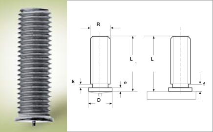
Características Pernos de acuerdo con norma EN ISO 13918
| R | L + 0,6 | D ± 0,2 | e | K max | L |
|---|---|---|---|---|---|
| M3 | 5-4o | 4,5 | 0,7 | 1,5 | = L1 – 0,3 |
| M4 | 6-45 | 5,5 | 1,4 | 1,5 | = L1 – 0,3 |
| M5 | 6-50 | 6,5 | 0,8 | 2 | = L1 – 0,3 |
| M6 | 8-55 | 7,5 | – | 2 | = L1 – 0,3 |
| M8 | 10-60 | 9 | 1,4 | 3 | = L1 – 0,3 |